Why you should care — quick framing
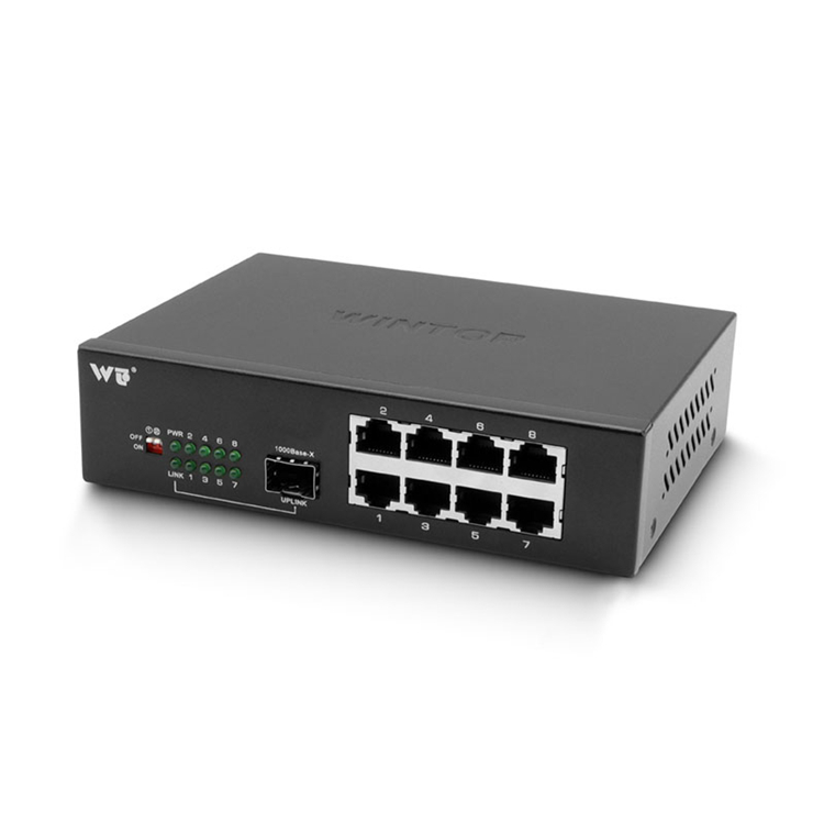
Multi-path interference in QSFP28 SR4 parallel ribbons eats link margin and makes 100G ports flaky. Since IEEE 802.3ba formally laid out 100G Ethernet back in 2010, data centres and campus backbones have pushed denser optics and tighter tolerances; that matters when QSFP28 transceivers, MPO ribbon cables and patching meet. If you need bulk replacements or bridging gear, look through recognised media converters manufacturers first — they often ship tested converter modules that help isolate link problems early.

Framework: five practical layers to diagnose and reduce MPI
Treat the problem like a stack. Follow these layers in order and you’ll chop sources of multi-path interference (MPI) efficiently:
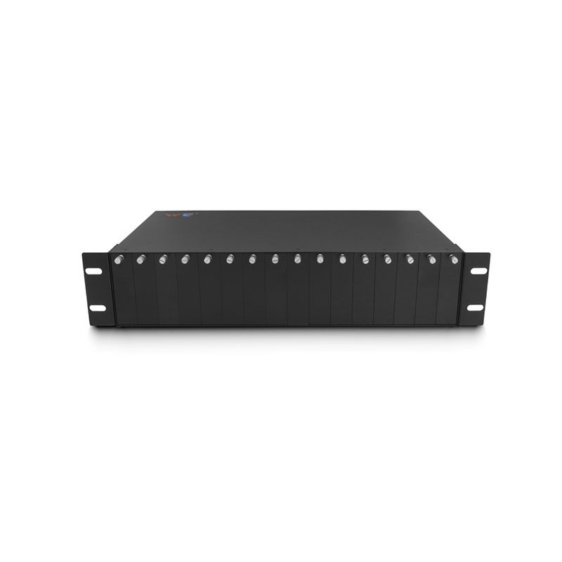
– Inventory and mapping: list all QSFP28 SR4 ports, MTP/MPO trunks, patch panels and transceiver firmware versions. – Physical cleanliness and mating: clean ferrules, check ferrule endfaces and confirm correct MPO polarity and keying. Small dust or reversed polarity kills performance. – Cable and connector quality: measure insertion loss and patch loss to confirm cables meet SR4 channel budget; replace suspect parallel ribbons. – Transceiver tuning: verify TX power, RX sensitivity and enable appropriate equalization or DFE where supported. Keep firmware consistent. – Segmentation with converters: isolate suspect spans using short loopbacks or a 10g media converter to convert and test single-lambda links before reintroducing the full 4-lane parallel ribbon.
Diagnostics and the right tools
Practical diagnostics use measurable checkpoints: insertion loss, return loss and eye diagrams or BER sweep. OTDRs help for long trunks but don’t substitute for loss and BER tests on short multi-fibre ribbons. Use a calibrated light source and power meter on each lane, then run a PRBS BER test from the transceiver pair. Record results — you want repeatable numbers, not guesses.
Common mistakes that prolong outages
– Swapping in “equivalent” cables without testing: vendors differ in MPO polish and ferrule concentricity. – Ignoring polarity: SR4 assumes correct lane order; a single swapped fibre causes lane mismatch and inter-lane interference. – Overlooking patch panel wear: repeated mating cycles change loss and crosstalk characteristics. – Relying only on visual inspection: a clean-looking endface can still show high insertion loss under power.
Tune decisions with trade-offs
Sometimes the fastest fix isn’t replacement. If lanes show marginal loss but good BER after equalization, you can leave connectors and schedule full replacement during a maintenance window. If BER remains unstable, replace the shortest suspect link first — the cheapest and quickest test. Use media converters when you want to validate single-lambda behavior or temporarily break a parallel ribbon into debug-friendly channels — these devices simplify the electrical-optical boundary when troubleshooting complex SR4 behaviour.
Validation checklist before you declare the link healthy
Run these final checks in order: confirm per-lane TX/RX power within spec, verify BER below your SLA threshold at expected load, and do an in-service stress test (traffic burst simulation) for at least 10–15 minutes. Keep logs for comparison after any hardware swap.
Advisory: three golden rules for choosing strategies or tools
1) Prioritise measurement over assumption — pick tools that give per-lane BER and power. 2) Match connector polish and vendor tolerances when replacing ribbon cables; consistency beats cheaper, mixed-stock parts. 3) Use media converters and short-loop transceivers to isolate lanes quickly — they cut diagnostic time and reduce downtime risk.
Real-world anchor: networks built on the IEEE 802.3ba standard depend on disciplined physical-layer practice — it’s not exotic, it’s expected. Fixes that follow this framework reduce repeat failures and make upgrades predictable. WINTOP.
Sharp rules, practical checks — that’s how you keep 100G SR4 links honest. —