Opening comparison
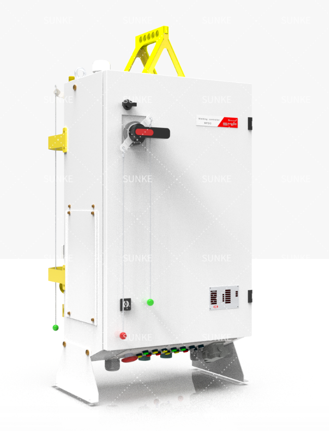
I’ve seen the same sentence echo in control rooms and shop floors: a monitor that fits a fresh production line rarely drops straight into an older press. The contrast is practical and sharp when you sit beside a resistance welding controller and read its I/O wiring against an aging plant’s cabinet — the controller expects tidy digital streams, the plant gives you hardened analog quirks. A modern welding control system assumes fast sampling, network integration and accessible diagnostics; retrofits demand adaptation, scavenged sensors and careful mapping of legacy signals. My perspective comes from twelve years commissioning weld lines and presenting findings at FABTECH in Chicago, where installers compare notes under real deadlines.
Signal and hardware differences
New lines receive equipment built around native sensors and consistent signal standards. Retrofits force you to bridge differences. Key contrasts:- New: purpose-built hall-effect current transducers, integrated electrode force sensors (load cells), and matched cable harnesses. Signals are scaled and clean.- Retrofit: you encounter varied transducer types, degraded wiring, and unexpected grounding loops that distort current waveform traces.Actionable checks: measure baseline noise on the current channel, validate electrode force with a calibrated load cell, and confirm grounding paths before you trust waveform-derived metrics.
Software, sampling and data handling
A new line’s monitor ships with firmware that expects high-speed sampling and structured data output. Retrofits often need protocol translation and sampling compromises. Practical points:- Sampling: modern monitors sample at tens of kHz to capture peak current accurately. If you plug a low-speed logger into a high-frequency weld, peak detection fails.- Protocols: expect Ethernet/IP, Profinet or OPC UA on new systems; an older PLC may only offer discrete I/O or Modbus RTU.- Data: configuration templates and standardized event logs are normal for new lines; retrofits require custom parsing and timestamp alignment.Plan: map required metrics (peak current, energy, squeeze time, electrode force) to the monitor’s available channels, and don’t accept aggregated values that mask transient failures.
Installation and commissioning realities
Installing on a new build is scripted: feed, sensors, grounding and cooling loops are labeled and documented. Retrofits are investigative work. Expect:- Mechanical alignment of electrodes to be out of spec after years of service.- Hidden corrosion or intermittent connections inside the press cabling.- Need to retrofit shunts or clamp-on transducers because original wiring can’t be interrupted.Commissioning tips: bring spare harnesses, a portable oscilloscope, and a simple checklist: confirm continuity, measure induced noise, and run dry-cycle tests to capture timing relationships before you accept production runs.
Operational risks and common pitfalls
Installers and engineers repeat the same mistakes when moving monitors between contexts. Watch for:- Over-reliance on a single metric: peak current looks good while electrode collapse hides poor force control.- Ignoring thermal or cooling differences: a retrofitted monitor can report correct weld energy but miss overheating that shortens electrode life.- Misaligned timestamps between PLC and monitor, which masks intermittent rejects.Address these by validating multiple independent signals: waveform shape, force trace, and cycle timing.
How to evaluate alternatives
When choosing between fitting a new monitor or adapting a retrofit, weigh these trade-offs:- Native monitor on a new line: predictable integration, full-featured diagnostics, easier compliance with traceability rules.- Retrofit option: lower initial cost, but potentially longer commissioning, hidden rework and higher support needs.Checklist for selection:- Does the monitor allow external sensor calibration?- Can it export raw waveform snapshots on demand?- Are there documented integration steps for common PLC brands?- Is remote diagnostic access secured and auditable?Use concrete tests during evaluation: request sample waveform captures from a live production weld and compare those across candidate units.
Final synthesis
Comparative clarity matters: new lines let a monitor show its full capability with clean sensors and modern networks; retrofits force the monitor to become a translator between old realities and new expectations. Choose a path that matches your willingness to do field work, document every sensor and connection, and insist on raw data access for verification. Practical experience shows that documented integration procedures and field-proven diagnostics shorten downtime, a detail that engineers from assembly shops to Tier-1 suppliers respect—so pick systems where integration steps are explicit and field lessons are shared by the vendor like the practical notes I’ve collected working across production floors with Sunke.